Optical performance test for infrared sensing device
|
Short Description |
On-site test lab for presence and motion detection |
|
Description and feature list |
On-site test lab may be leased on a hourly/daily/weekly rate for customer use. |
|
Proposed Engineering Service |
Verification;Testing;Safety;Certification;Quality Mgt;Consulting |
|
Proposed Design Service |
Verification;Testing;Certification;Consulting |
This is a service that tests and validates your device or optics for motion, presence, and LiDAR in terms of optical performance.
Please feel free to contact ashton@fresnelfactory.com for further question.
Typical service time is from 2 weeks to 4weeks.


Test machine specification
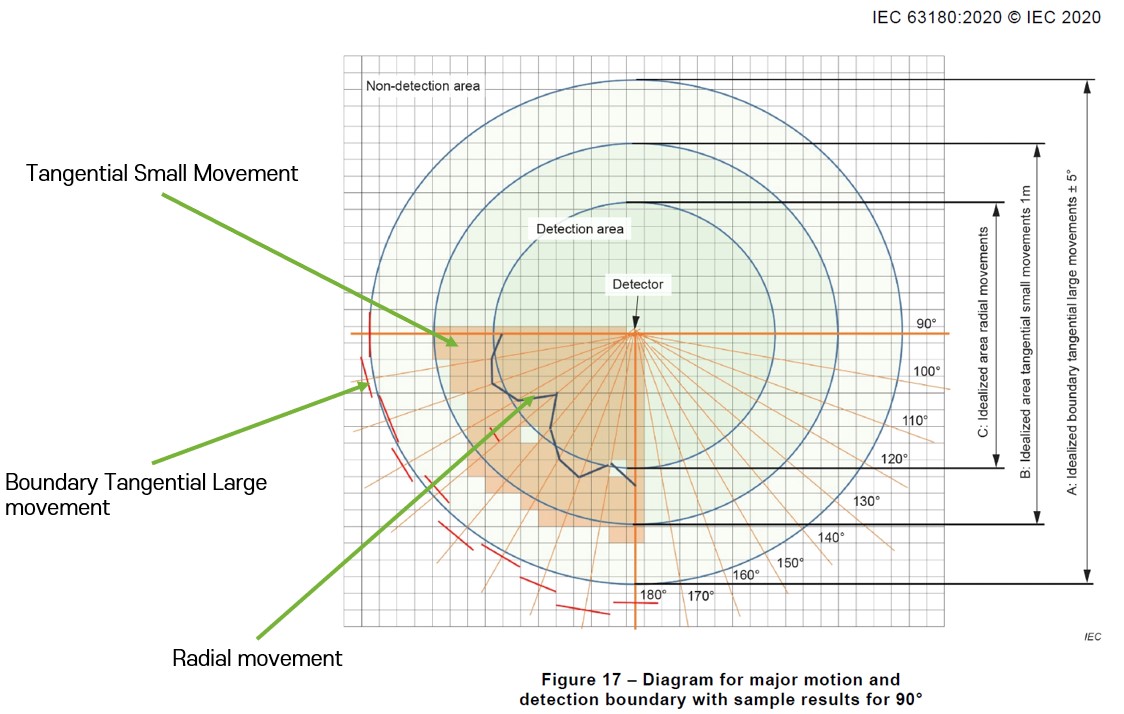
- Fresnel Factory’s 5-axis CNC automated test systems perform motion detector measurement in a full 360°circle for only one measurement cycle.
- The maximum diameter of Detection area is 45.0 meters, and maximum sensor mounting height is 8.5 meters. (Scale ratio is 1:5)
- Scaled test dummy of human body (1:5 ratio) according to IEC 63180 standard
- Numerical control of temperature (dummy leg, body, head).
- Automated test system can measure tangential, radial, small tangential movement in fully automatic mode according to all requirements of IEC 63180 standard.
- Proven repeatability.
- Customization of measurement condition.
All tests to be conducted according to IEC 63180.
- For Tangential motion, grid cells may be 1m square as defined in the standard.
- For Radial motion, 10° steps shall be used as defined in the standard. Target should start as far away from the detector as test setup allows.
- For Detection boundary, rotation angle -5° to +5° shall be used as defined in the standard. Distance steps of 1m may be used.
- Fully capable for IEC 63180 “Methods of measurement and declaration of the detection range of detectors – Passive infrared detectors for major and minor motion detection”
Please check below information for better understanding what kind of “optical performance test for infrared sensing device”
- Understanding what is the role of lens in the system
- To remove gap between simulation and real product
- Understanding what is the role of lens in the system
The optical sensor, such as TMOS detects light intensity within its detectable area. The detectable area consists with field of view, distance and direction.
Role of lenses are changing those factors according to applications and use cases.
Not only performance side, but also lens works as aesthetic parts. A active area of lens should be exposed to outside without any blocking. From this reason, optic engineer is better to join a beginning of mechanical and industrial design phase.
As example, TMOS sensor itself can detect 6meter distance, but TMOS sensor with PF63-10 can detects 16meter distance.
As you can feel lenses are very important in Optical sensors. most of the optical sensors has Lenses inside of their mechanism.
Check the No. 5. Define your requirement for details.

- To remove gap between simulation and real product
Even if your design partner is a highly skilled optical designer or a mold and injection technology expert, there can still be a difference of 20% or more between predicted design performance and actual performance in reality. This is often because optical designers may not understand molds and injection, and mold and injection technology experts may not understand optical design. In addition, depending on production conditions and additives, there may be an additional 5% or more difference in performance. Therefore, it is essential to evaluate the manufactured optics and the device in which the optics are used to confirm whether the goals have been achieved and to tune them accordingly.
- Contact
USA : Frank Yim / frankyim@fresnelfactory.com
Global : Ashton / ashton@fresnelfactory.com
